
Milling operations are broadly classified as peripheral milling and face milling: Peripheral Milling. Generally, peripheral, or plain, milling is accomplished with the workpiece surface mounted to the milling machine table and the milling cutter mounted on a standard milling machine arbor. The arbor is well supported in a horizontal plane between the milling machine spindle and one or more arbor supports. For plain milling, the workpiece is generally clamped directly to the table or supported in a vise. The milling machine table should be checked for alignment before starting to make a cut. If the workpiece surface that is to be milled is at an angle to the base plane of the piece, the workpiece should be mounted in a universal vise or an adjustable angle plate. The holding device should be adjusted so that the workpiece surface is parallel to the table of the milling machine. For plain milling operations, a plain milling cutter should be used. Deeper cuts may generally be taken when narrow cutters are used than with wide cutters. The choice of milling cutters should be based on the size of the workpiece. If a wide area is to be milled, fewer traverses will be required using a wide cut. The milling cutter is positioned on the arbor with sleeves so that it is as close as possible to the milling machine spindle, while maintaining sufficient clearance between the vise and the milling machine column. This practice reduces torque in the arbor and permits more rigid support for the cutter.
If large quantities of metal are to be removed, a coarse tooth cutter should be used for roughing and a finer tooth cutter should be used for finishing. A relatively slow cutting speed and a fast table feed should be used for roughing, and a relatively fast cutting speed, and a slow table feed used for finishing. The surface should be checked for accuracy after each completed cut.
Slotting.
Also called slot milling, the width of the cutter is less than the width of the workpiece. It is used to make the slot in the workpiece. Thin slots can be made by using very thin milling cutters. The workpiece can be cut into two pieces by making a very thin slot throughout the depth of the workpiece. Cutting the workpiece this way is called saw milling.
Side Milling.
The side milling is the production of a flat vertical surface on the side of a work piece by using a side-milling cutter. The depth of cut is adjusted by rotating the vertical feed screw of the table.
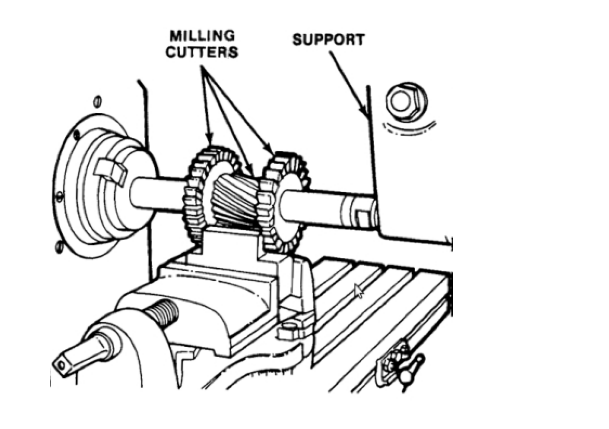
Straddle Milling.
When two or more parallel vertical surfaces are machined at a single cut, the operation is called straddle milling. Straddle milling is accomplished by mounting two side milling cutters on the same arbor, set apart so that they straddle the workpiece. The diagram below illustrates a typical example of straddle milling. In this case a spline is being cut, but the same operation may be applied when cutting squares or hexagons on the end of a cylindrical workpiece. The workpiece is usually mounted between centers in the indexing fixture, or mounted vertically in a swivel vise. The two side milling cutters are separated by spacers, washers, and shims so that the distance between the cutting teeth of the cutters is exactly equal to the width of the workpiece area required. When cutting a square by this method, two opposite sides of the square are cut, then the spindle of the indexing fixture or the swivel vise is rotated 90 ° and the other two sides of the workpiece are straddle milled.
Gang milling.
The term applied to an operation in which two or more milling cutters are used together on one arbor when cutting horizontal surfaces. The usual method is to mount two or more milling cutters of different diameters, shapes and/ or widths on an arbor as shown in the following diagram. The possible cutter combinations are unlimited and are determined in each case by the nature of the job.
Form Milling.
The process of machining special contours composed of curves and straight lines, or entirely of curves, at a single cut. This is done with formed milling cutters, shaped to the contour to be cut, or with a fly cutter ground for the job. The more common form milling operations involve milling half-round recesses and beads and quarter-round radii on the workpieces. This operation is accomplished by using convex, concave, and corner rounding milling cutters ground to the desired circle diameter. Other jobs for formed milling cutters include milling intricate patterns on workpieces and milling several complex surfaces in a single cut, such as produced by gang milling.
Up Milling.
Also called conventional milling; in this case movement of cutter teeth is opposite to the direction of feed motion. Down Milling. Also called climb milling; in this case direction of cutter motion is the same so that of direction of feed motion.
Face Milling.
Face milling cutters, end milling cutters, and side milling cutters are used for face milling operations. The size and nature of the workpiece determines the type and size of the cutter required. In face milling, the teeth on the periphery of the cutter does most of the cutting. However, when the cutter is properly ground, the face teeth remove a small quantity of stock which is left as a result of the springing of the workpiece or cutter, thereby producing a finer finish. It is important in face milling to have the cutter securely mounted and to see that all end play or sloppiness in the machine spindle is eliminated.
When face milling, the workpiece may be clamped to the table or angle plate, or supported in a vise, fixture, or jig. Large surfaces are generally face milled on a vertical milling machine with the workpiece clamped directly to the milling machine table to simplify handling and clamping operations. The following diagram illustrates face milling performed with a swivel cutter head milling machine with its spindle in a vertical position. The workpiece is supported parallel to the table in a swivel vise. Angular surfaces can also be face milled on a swivel cutter head milling machine. In this case, the workpiece is mounted to the table and the cutter head is swiveled to bring the end milling cutter perpendicular to the surface to be produced. During face milling operations, the workpiece should be fed against the milling cutter so that the pressure of the cut is downward, thereby holding the work against the table. Whenever possible, the edge of the workpiece should be in line with the center of the cutter. This position of the workpiece, in relation to the cutter, will help eliminate slippage.
When setting the depth of the cut, the workpiece should be brought up to just touch the revolving cutter. After a cut has been made from this setting, a measurement of the workpiece is taken. The graduated dial on the traverse feed is then locked and used as a guide in determining the depth of the cut. When starting the cut, the workpiece should be moved so that the cutter is nearly in contact with its edge, after which the automatic feed may be engaged. When a cut is started by hand, care must be taken to avoid pushing the corner of the workpiece between the teeth of the cutter too quickly, as this may result in cutter tooth breakage. In order to prevent time wasting during the operation, the feed trips should be adjusted to stop table travel just as the cutter clears the workpiece.
Conventional Face Milling.
In this case, the diameter of the milling cutter is greater than the width of the workpiece. The milling cutter overhangs both sides of the workpiece.
Partial Face Milling.
Here, the milling cutter overhangs on the workpiece on one side only.
End Milling.
End milling primarily differs from other milling processes due to the type of tooling that is used for abrading a given material. Unlike cutters and drill bits, end mills have cutting teeth on the sides and end of the mill. Additionally, the milling applications for the end mill are unique. End mills are typically used in applications requiring profile milling, tracer milling, shape milling, face milling, and plunging. This operation is used for non-conventional non-conventional or unique applications,
Profile Milling.
This is similar to end milling in which the outer side periphery of a flat part is machined (milled).
Pocket Milling.
This is a selective portion milling on the flat surface of the workpiece used to make shallow packets. Surface Contouring. In this operation, a ball nose cutter if feedback and forth across the workpiece along a curvilinear path at short intervals. This creates the required contours on the surface of the workpiece. This operation is used to make contours of molds and dies and this time the operation is called die sinking.
learn more: CNC Milling Service; CNC Machining Parts Supplier